+49 9622 719910

Frequently asked questions – FAQ

In the FAQ section, we have compiled general information on frequently asked questions, interesting facts and helpful technology tips for you. The topics are organised according to our product categories.

Inverters

How to find your inverter

+

Calculating the output power

To determine which inverter model you need, simply add up the outputs (W or VA) of your required  electrical consumers. However, you should bear in mind that certain loads require larger power reserves (5 to 10 times) due to their increased starting current. If you are not sure which inverter is right for you, simply contact us. We will be happy to advise you and help you choose the right inverter and accessories.
 
Recommended
inverter
Conventional
consumers
Recommended
battery capacity
Conductor
cross section
Conductor
length
DSW-300
(12 V or 24 V)
Multimedia devices = 45 Ah = 16 mm2
= 25 mm2
1 m, 2 m, 3 m
3 m, 4 m
DSW-600
(12 V or 24 V)
Multimedia devices Electrical appliances 500 W = 75 Ah = 16 mm2
= 25 mm2
1 m, 2 m, 3 m3)
1 m, 2 m, 3 m, 4 m
DSW-1200
(12 V or 24 V)
Multimedia devices Electrical appliances 500 W Electrical appliances 1000 W = 75 Ah = 25 mm2
= 35 mm2
= 50 mm2
1 m3), 2 m3), 3 m3), 4 m3)
1 m, 2 m, 3 m3)
1 m, 2 m, 3 m, 4 m
DSW-2000
2000 W
12 V1)
24 V
Multimedia devices Electrical appliances 500 W Electrical appliances 1000 W Electrical appliances Starting current High power electrical appliances = 100 Ah = 35 mm2
= 50 mm2
1 m3), 2 m3), 3 m3)
1 m, 2 m, 3 m, 4 m
DSW-2000-Synchron2)
4000 W (2 x 2000 W)
12 V1)
Multimedia devices Electrical appliances 500 W Electrical appliances 1000 W Electrical appliances Starting current High power electrical appliances = 200 Ah 2 x 50 mm2 1 m, 2 m, 3 m, 4 m

1) Due to the high current flow, only use conductors to the battery with a minimum cross section of 50 mm2 for the 12 V versions of the DSW-2000 and DSW-2000-Synchron.

2) If the DSW-2000 is not sufficient, or if you may require even more power in the future, we recommend using the DSW-2000 Synchron. This version can be interconnected to a second DSW-2000-Synchron device to achieve a continuous capacity of 4000 W.

3) Only suitable for the 24 V version.


Multimedia devices
Multimedia devices/small consumers (up to 300 W)
e.g. mobile phones, laptops, TV set, radios, charging devices
Electrical appliances 500 W
Electrical appliances/tools (up to 500 W)
e.g. jigsaw, electric whisk, hedge clippers, hand-held blender
Electrical appliances 1000 W
Electrical appliances/tools (up to 1000 W)
e.g. angle grinder, coffee machine, hammer drill
Electrical appliances Starting current
Electrical appliances with increased starting current
e.g. pumps, compressors, refrigerators, air conditioning devices
High power electrical appliances
Electrical appliances/tools with high power consumption
e.g. hair dryers, vacuum cleaners, fan heaters, electric lawn
mowers
 
Important: Cross-section of the connection cable
For safety reasons, we recommend that you always use a sufficiently dimensioned original connection cable. The original IVT connection cables are optimally matched to the inverter series and are additionally protected with a 200 A fuse. You will find the appropriate connection cables on the respective product page.
 
Our recommendation: Installing a second battery
Using a second battery is particularly reasonable when an inverter is used in a vehicle. If the second battery is discharged, the engine can still be started reliably using the vehicle's starter battery.

A battery system consisting of two batteries and a second battery charger is also a useful addition in conjunction with a solar island system. This is a simple and cost-effective way of ensuring the energy supply for particularly important consumers at all times.
 
E-1

IVT inverters may be installed in vehicles with road approval
The Digital Sine Wave Inverters fulfil the legal requirements of the ECE regulation and are therefore E-certified. They are suitable for permanent installation in all road-legal vehicles, whether passenger cars, commercial vehicles or other vehicles with 12 V or 24 V on-board voltage.

Calculating the output power

To determine which inverter model you need, simply add up the outputs (W or VA) of your required  electrical consumers. However, you should bear in mind that certain loads require larger power reserves (5 to 10 times) due to their increased starting current. If you are not sure which inverter is right for you, simply contact us. We will be happy to advise you and help you choose the right inverter and accessories.
 
Recommended inverter

Digital Sine Wave Inverters DSW-300,
300 W, 12 V or 24 V

Conventional consumers:
Multimedia devices/small consumers up to 300 W
Recommended battery capacity: = 45 Ah
Suitable connection cable (cross-section | length):
16 mm2 | 1 m, 2 m, 3 m
25 mm2 | 3 m, 4 m

Digital Sine Wave Inverters DSW-600
600 W, 12 V or 24 V

Conventional consumers:
Electrical appliances/tools up to 500 W
Recommended battery capacity: = 75 Ah
Suitable connection cable (cross-section | length):
16 mm2 | 1 m, 2 m, 3 m3)
25 mm2 | 3 m, 4 m
Digital Sine Wave Inverters DSW-1200,
1200 W, 12 V or 24 V

Conventional consumers:
Electrical appliances up to 1000 W
Electrical appliances with increased starting current
Recommended battery capacity: = 75 Ah
Suitable connection cable (cross-section | length):
25 mm2 | 1 m3), 2 m3), 3 m3), 4 m3)
35 mm2 | 1 m, 2 m, 3 m3)
50 mm2 | 1 m, 2 m, 3 m, 4 m
Digital Sine Wave Inverters DSW-2000
2000 W, 12 V1) or 24 V

Conventional consumers:
Electrical appliances with high power consumption
Electrical appliances with increased starting current
Recommended battery capacity: = 100 Ah
Suitable connection cable (cross-section | length):
35 mm2 | 1 m3), 2 m3), 3 m3)
50 mm2 | 1 m, 2 m, 3 m, 4 m
Digital Sine Wave Inverters DSW-2000-Synchron
4000 W (2 x 2000 W), 12 V1)

Conventional consumers:
Electrical appliances with high power consumption
Electrical appliances with increased starting current
Recommended battery capacity: = 200 Ah
Suitable connection cable (cross-section | length):
2 x 50 mm2 | 1 m, 2 m, 3 m, 4 m

1) Due to the high current flow, only use conductors to the battery with a minimum cross section of 50 mm2 for the 12 V versions of the DSW-2000 and DSW-2000-Synchron.

2) If the DSW-2000 is not sufficient, or if you may require even more power in the future, we recommend using the DSW-2000 Synchron. This version can be interconnected to a second DSW-2000-Synchron device to achieve a continuous capacity of 4000 W.

3) Only suitable for the 24 V version.


Important: Cross-section of the connection cable
For safety reasons, we recommend that you always use a sufficiently dimensioned original connection cable. The original IVT connection cables are optimally matched to the inverter series and are additionally protected with a 200 A fuse. You will find the appropriate connection cables on the respective product page.
 
Our recommendation: Installing a second battery
Using a second battery is particularly reasonable when an inverter is used in a vehicle. If the second battery is discharged, the engine can still be started reliably using the vehicle's starter battery.

A battery system consisting of two batteries and a second battery charger is also a useful addition in conjunction with a solar island system. This is a simple and cost-effective way of ensuring the energy supply for particularly important consumers at all times.
 
E-1

IVT inverters may be installed in vehicles with road approval
The Digital Sine Wave Inverters fulfil the legal requirements of the ECE regulation and are therefore E-certified. They are suitable for permanent installation in all road-legal vehicles, whether passenger cars, commercial vehicles or other vehicles with 12 V or 24 V on-board voltage.

Convenient alternatives for small consumers up to max. 150 W - Sine wave inverters with car plug

+

Sine wave inverters for the cigarette lighter socket

The SW-100, 12 V and SW-150, 12 V or SW-150, 24 V sine wave inverters do not need to be permanently installed, but can be flexibly connected via the 12 V or 24 V car plug in the vehicle. The small SW inverters are compact and lightweight and can be used for a wide range of applications, not least due to their extensive protective functions.
 
Sinus Inverter IVT SW-100, 12 V, 100 W Sinus Inverter IVT SW-100, 12 V, 100 W
Real sine wave alternating voltage 230 V/50 Hz
Continuous output power 100 W | Peak output power 200 W
Flexible connection via 12 V car adapter
Item no. 430012
To the product >
Sinus Inverter IVT SW-150, 12 V, 150 W Sinus Inverter IVT SW-150, 12 V, 150 W
Real sine wave alternating voltage 230 V/50 Hz
Continuous output power 150 W | Peak output power 300 W
Flexible connection via 12 V car adapter
Item no. 430000
To the product >
Sinus Inverter IVT SW-150, 24 V, 150 W Sinus Inverter IVT SW-150, 24 V, 150 W
Real sine wave alternating voltage 230 V/50 Hz
Continuous output power 150 W | Peak output power 300 W
Flexible connection via 24 V car adapter
Item no. 430001
To the product >

Portable and flexibly rechargeable – the individual Power Stations from IVT

+

IVT Portable Power Stations


The portable IVT Power Stations can be used in a variety of mobile and stationary applications

The IVT Mobile Power Stations are a another option for flexibly supplying 12 V and 230 V consumers with power.
The PS-300 Mobile Power Station is suitable for small consumers up to max. 300 W. The integrated sinus inverter SW-300 generates a pure sine wave with 230 V/50 Hz at the output. The PS-300 has one 12 V DC and one 230 V AC output. Both outputs can be used simultaneously or separately. The portable Power Box can be recharged using a 230 V charger as well as in the car using a 12 V cigarette lighter socket. The charger and the 12 V car charging adapter are included in the delivery. Extensive protective functions are integrated as standard.
 
Power Station IVT PS-300 with integrated sine wave inverter Power Station IVT PS-300 with integrated 300 W sine wave inverter
Pure sine wave
Continuous output power 300 W | Peak output power 600 W
AGM battery 12 V, 20 Ah
230 V AC and 12 V DC load output
Item no. 430100
To the product >
 

Individually customisable power stations – rechargeable with solar, in the car and at a 230 V mains voltage

For electronic devices with a higher output, we recommend the customised power stations.

The customised Power Stations are available with an output power of 600 W, 1200 W and 2000 W as a standard. The robust power boxes are ideal for commercial and private applications thanks to their well thought-out design, high-quality components, simple connection as well as flexible charging options.
 

If required, individual components of the power stations can also be replaced, omitted or added. Do not hesitate to contact us. We will find the right solution for you.

 
Portable Power Station IVT PS-600, 600W Portable Power Station IVT PS-600 with integrated 600 W Digital Sine Wave Inverter
True sine wave 230 V/50 Hz
Continuous output power 600 W | Peak output power 1200 W
Powerful 12.8 V/80 Ah LiFePO4 battery with app function
Switchable load outputs: 230 V AC, 12 V DC, 2 x 5 V USB
Customisable and much more
Item no. 430089
To the product >
Portable Power Station IVT PS-1200, 1200 W Portable Power Station IVT PS-1200 with integrated 1200 W Digital Sine Wave Inverter
True sine wave 230 V/50 Hz
Continuous output power 1200 W | Peak output power 2400 W
Powerful 12.8 V/100 Ah LiFePO4 battery with app function
Switchable load outputs: 230 V AC, 12 V DC, 2 x 5 V USB
Customisable and much more
Item no. 430074
To the product >
Portable Power Station IVT PS-2000, 2000 W Portable Power Station IVT PS-2000 with integrated 2000 W Digital Sine Wave Inverter
True sine wave 230 V/50 Hz
Continuous output power 1200 W | Peak output power 2400 W
Powerful 12.8 V/100 Ah LiFePO4 battery with app function
Switchable load outputs: 230 V AC, 12 V DC, 2 x 5 V USB
Customisable and much more
Item no. 430090
To the product >

Socket standards and mains voltages in Europe

+

Socket outlet standards and mains voltages – the most important information at a glance

In Europe, plug types C (Euro plug) and F (Schuko plug®) are widely used. The voltage range is between 220 - 240 V/50 Hz. The flat Euro plug generally also fits in other European countries, although an adapter is sometimes required for the Schuko plug®.

Summary of the most important output sockets and plug types
 
Connector type: F, C Connector type: G Connector type: E, C Connector type: C Connector type: C Connector type: K, C Connector type: L, C Connector type: J, C Connector type: D


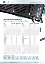
Overview of country-specific mains voltages and plug types
Download Pdf >
 
 
The inverter output socket can be replaced on request
If the IVT Digital Sine Wave inverters are to be used abroad, it is possible for us as manufacturer to make country-specific adaptations. For example, the standard 230 V safety socket, suitable for plug type F and C, can be replaced with a different one. We will be happy to provide you with a customised quotation.

Charging Technology

How to find the right charger for your car, motorbike and many more

+

Easy-to-use battery chargers – safe and versatile

Charging process and float charging tailored to the respective battery type
A properly charged and well-maintained battery has a significantly longer service life than one that has only been partially charged or even deeply discharged over a longer period of time.

Staudte Hirsch chargers are suitable for numerous vehicles and for recharging 12 V solar batteries with mains power
In line with our company philosophy, as a manufacturer you will find inexpensive, small chargers for occasional use or for trickle charging. We also offer all-round chargers with a special motorbike mode for 6 V and 12 V lead batteries as well as multi-stage battery chargers for demanding users.


Suitable for passenger cars
Passenger
car

Suitable for transporters
Transporter
 

Suitable for motorhomes
Motorhome
 

Suitable for caravans
Caravan
 

Suitable for trucks
Truck
 

Suitable for coaches
Coach
 
Suitable for construction machinery
Construction
machinery
Suitable for tractor
Tractor
 
Suitable for motorboat
Motorboat
 
Suitable for sailing boat
Sailing
boat
Suitable for motorbike
Motorbike
 
Suitable for scooters
Scooter
 
Suitable for moped
Moped
 
Suitable for Quad
Quad
 
Suitable for riding lawn mowers
Lawn
mower
Suitable for electric wheelchair
Electric
wheelchair
Suitable for Golf Trolley
Golf
trolley
Suitable for snowmobiles
Snowmobile
 
Suitable for jet skis
Jet Ski
 
Suitable for 12 V solar systems
Solar
system


The following table contains all the key data on the Staudte Hirsch battery chargers

Depending on the area of application, different models with a wide range of features and functions are available. 

The user-friendly Staudte Hirsch automatic chargers are available as standard with a charging current between 1 A and 16 A, depending on the model.


Staudte Hirsch SH-3.110 Pb, 12 V, 1,5 A

Staudte Hirsch SH-3.120 6 V/12 V, 1 A

Staudte Hirsch SH-3.170 6 V/12 V, 2 A

Staudte Hirsch SH-3.130 6 V/12 V, 4,5 A

Staudte Hirsch SH-3.150 6 V/12 V, 10 A

Staudte Hirsch SH-3.160 12 V, 16 A

Battery
Charger

Staudte Hirsch
SH-3.110
Pb, 12 V, 1.5 A

Staudte Hirsch
SH-3.120
6 V/12 V, 1 A

Staudte Hirsch
SH-3.170
6 V/12 V, 2 A 

Staudte Hirsch
SH-3.130
6 V/12 V, 4.5 A

Staudte Hirsch
SH-3.150
6 V/12 V, 10 A

Staudte Hirsch
SH-3.160
12 V, 16 A
Charging method

IU

Multi-step Multi-step Multi-step Multi-step Multi-step
Charging current


Regular mode,
(max.)

1.5 A ± 10 %

1.0 A ± 10 %

2.0 A ± 10 %

4.5 A ± 10 %

10.0 A ± 10 %

16 A ± 10 %

Motorbike mode,
(max.)

1.0 A ± 10 % 

Battery capacity


Lead battery


Regular mode

2.0 - 35.0 Ah

from 1.2 Ah

from 2.0 Ah

from 14.0 Ah

from 20.0 Ah

from 30.0 Ah
Motorbike mode

from 1.2 Ah

Calcium battery

from 1.2 Ah

from 2.0 Ah

from 14.0 Ah

from 25.0 Ah

from 30.0 Ah
Lithium battery

from 1.2 Ah

from 2.0 Ah

from 25.0 Ah

from 25.0 Ah

from 30.0 Ah
Rechargeable battery types

Lead-acid, lead-gel

? ? ? ? ? ?

AGM

? o o ? ? ?

Calcium

o o o ? ?

Lithium

? ? ? ? ?
Charging mode & functions

Boost mode

? ?

12 V charging mode

? ? ? ? ? ?

6 V charging mode

? ? ?

Desulfation function

?

Automatic
regeneration mode

? ? ? ? ?

Float charging phase

? ? ? ? ? ?

Auto-memory function

? ? ? ? ?
General

Protection against short
circuit, reverse polarity
and overcharging

? ? ? ? ? ?
IP protection (housing)

IP 20

IP 20

IP 20

IP 65

IP 65

IP 20

Dimensions
(L x W x H), mm

110 x 70 x 40

110 x 70 x 40

110 x 70 x 40

203 x 67 x 48

242 x 102 x 60

242 x 102 x 60
Weight
(without accessories)

260 g

250 g

250 g

490 g

850 g

960 g
Item no. 331100 331200 331700 331300 331500 331600
?  = yes
o  = Charging possible, but not optimised for this battery type.
–  = no


Preview Product Info: Staudte Hirsch charger series | Overview of technical data and functions

 
Product overview Staudte Hirsch battery chargers

We have summarised the most important technical data for the Staudte Hirsch professional charger series for you in a concise table. 

Download Pdf >


Battery chargers – Modification according to your ideas possible

After prior consultation, our Staudte Hirsch chargers can be customised according to your individual requirements. Contact us, we will be happy to advise you and make you an offer for your individual device or series.

Easy-to-use battery chargers – safe and versatile

Charging process and float charging tailored to the respective battery type
A properly charged and well-maintained battery has a significantly longer service life than one that has only been partially charged or even deeply discharged over a longer period of time.

Staudte Hirsch chargers are suitable for numerous vehicles and for recharging 12 V solar batteries with mains power
In line with our company philosophy, as a manufacturer you will find inexpensive, small chargers for occasional use or for trickle charging. We also offer all-round chargers with a special motorbike mode for 6 V and 12 V lead batteries as well as multi-stage battery chargers for demanding users.
 

Depending on the area of application, different models with a wide range of features and functions are available. 

The user-friendly Staudte Hirsch automatic chargers are available as standard with a charging current between 1 A and 16 A, depending on the model.


Preview Product Info: Staudte Hirsch charger series | Overview of technical data and functions

 
Product overview Staudte Hirsch battery chargers

We have summarised the most important technical data for the Staudte Hirsch professional charger series for you in a concise table.

Download Pdf >


Modification according to your ideas possible

After prior consultation, our Staudte Hirsch chargers can be customised according to your individual requirements. Contact us, we will be happy to advise you and make you an offer for your individual device or series.

Overview of different battery charging methods

+
Graphic: Battery charging with constant current (I-charge)

Battery charging with constant current (I-charge)
With constant current charging, the battery in question is always charged with a constant current (Icharge). This prevents damage caused by excessive charging current. With this charging method, however, there is a risk that the battery will be overcharged. A suitable switch-off mechanism is therefore required.

Graphic: Battery charging with pulse charging

Battery charging with pulse charging
This is a special form of constant current charging. The charging pauses make it possible to precisely determine the battery voltage for the rest of the charging process. Pulse charging is also ideal for regenerating sulphated batteries.

Graphic: Battery charging with constant voltage (U-charge)

Battery charging with constant voltage (U-charging)
With constant voltage charging, the charging voltage (Ubat) is kept constant throughout the charging process. As a result, a higher current flows at the beginning of the charging process than at the end. The decreasing current towards the end of the charging process ensures that the battery is charged gently and completely.

Graphic: Battery charging according to the IU method

Battery charging using the IU method
The IU charging method combines the two charging methods mentioned above and utilises the advantages of both techniques. This allows a quick and gentle charge to be achieved in a simple manner.
 
Multi-stage battery charging process (IUoU charging)
This more complex, multi-stage charging technology also consists of a combination of the charging processes mentioned above. A microcontroller integrated into the charger ensures that the appropriate charging process is selected in order to charge the battery as quickly and efficiently as possible.

Lead or lithium – Which battery is better?

+

First things first – there are many arguments in favour of lithium

Lithium batteries are much lighter and have a significantly longer service life and number of charging cycles than lead batteries. In addition, lithium batteries score points with their significantly smaller volume, better charging efficiency, high energy density, low self-discharge and, last but not least, their significantly greater depth of discharge (lithium approx. 90 – 100 %, lead only approx. 50 %).
 
These significant advantages make lithium batteries a popular choice for a wide range of applications – from energy storage in portable devices to usage in vehicles and as high-performance storage for solar systems and much more.
 
However, this quality also comes at a price: if you want to buy a lithium battery, you will have to spend considerably more on the initial purchase than for a lead battery.

Infographic: Comparison of Lithium and AGM batteries | IVT GmbH


Is it possible to replace a lead-acid battery with a lithium battery?

As a rule, a lead-acid, lead-gel or AGM battery can be replaced with a LiFePO4 battery. However, the existing charging profiles of the existing charging devices/chargers must be checked and adjusted if necessary. Use suitable chargers with a maximum end-of-charge voltage of 14.6 V. Even simple lead-gel, lead-acid and AGM battery chargers can damage the LiFePO4 battery when first connected. Check the charging parameters of the respective charger in advance.

The best way to charge a Lithium battery

+
Staudte Hirsch battery charger when charging the car battery in the engine compartment
 

The best way to charge a LiFePO4 battery

  1. Only use chargers suitable for LiFePO4 cells with a maximum end-of-charge voltage of 14.6 V. Even simple lead, gel, acid and AGM battery chargers can damage the LiFePO4 battery when first connected. Check the charging parameters of the respective charger in advance.
  2. Observe the maximum charging current of your battery; this must not be exceeded at any time.
  3. Stop the charging process if the battery management system (BMS) cancels the charging process and check the battery and the charging parameters.
  4. Disconnect the charger if it will not be used for a longer period of time.
  5. Charge your LiFePO4 battery within 15 days of a low state of charge of approx. 20 % or after disconnection due to undervoltage to ensure maximum service life.
  6. Our batteries are approx. 80 % charged on delivery. We therefore always recommend fully charging a new battery before use. Observe the specifications for parallel or serial connection of the batteries according to the instructions.


How to store and winterise a LiFePO4 battery correctly

  1. Charge your LiFePO4 battery to 60 - 80 % of its capacity before storage.
  2. Disconnect your LiFePO4 battery from all loads and consumers before storage.
  3. Protect the pole contacts from short circuits by covering them.
  4. If stored for longer periods, the LiFePO4 battery must be recharged to 60 - 80 % every 6 months.
  5. Temperatures down to -20 °C do not damage the battery cell. It is therefore not necessary to remove the battery in most cases. In general, however, care should be taken to ensure that very cold batteries are slowly adjusted to the ambient temperature. Rapid heating can lead to condensation forming inside the housing and damage to the battery.
  6. Never use a trickle charger for winter storage.

Useful tips for handling lead batteries

+
Staudte Hirsch battery charger when charging the car battery in the engine compartment


1. Always select the right charger for your battery

Batteries can only be charged gently and fully with a suitable charger. Always compare the technical data of the charger with that of the battery.
 

2. Fully charge the battery before using it for the first time

In order to utilise the full capacity of your battery, a full charge is a basic requirement.
 

3. Protect your battery from harmful deep discharge

Deep discharge occurs when more than 60 % of the battery capacity has been used up. Use loads that have deep discharge protection.


4. Recharge your battery as often as possible

This prolongs the service life and prevents harmful deep discharging. The so-called "memory effect" does not occur with lead batteries.
 

5. Never leave your battery discharged

If discharged batteries are not recharged for a longer period of time, there is a risk that the natural self-discharge will lead to a damaging deep discharge.
 

6. Avoid charging and discharging your battery at the same time

Charging a battery while the load is switched on can lead to excessive heating of the charger or battery.
 

7. Always keep your battery ready for use

By using chargers with float charging, you ensure that a loss of capacity due to self-discharge is compensated and that your storage battery can be optimally utilised even after a long period of inactivity.

Solar Technology

Configuration of a solar island system

+

Graphic: Components of a solar island system


Installation of a 12 V/24 V off-grid system with DC and AC loads

Solar systems ensure an individual energy supply almost everywhere. An off-grid system for independent power supply with solar energy usually consists of several components, depending on the area of application:
 
Components of a solar island system
One or more solar module(s)
A solar charge controller
One or more solar battery(ies)
Optionally: a 12 V or 24 V direct current consumer (e.g. LED lighting)
An inverter if alternating current (230 V) is required
Alternating current consumer (e.g. 230 V AC lamps, TV set, tools)

Design and dimensioning of an off-grid solar system
  • The solar module (1) is connected to the solar controller (2). The two cables (±) used should be sufficiently sized to avoid line losses.
  • The charge controller (2) is connected to the solar battery (3) and, if necessary, to the DC consumers (4).
  • The charge controller should be dimensioned at least 10 % higher than the maximum current of the modules.
  • The battery cable and the cables to the loads should always contain an appropriate fuse.
  • The inverter (5) is always connected to the battery (3), never directly to the charge controller (2), as this can destroy the controller. This cable should also be fitted with a fuse.
  • The 230 V AC consumers (6) can be connected to the inverter (5).
  • The safety regulations for electrical installations must be observed during installation.
Please note: The solar batteries should be installed in a closed, dry room.

Why do you need a solar charge controller?

+
Solar controllers are used to supply solar energy to a suitable energy storage device in a controlled manner.

The sun's radiant energy is converted into electrical energy using a solar cell or solar module. The charge controller then ensures that this electrical energy is fed precisely and gently into a battery.

Solar controller: link between solar module and battery

Please note: Use suitable connection and connection cables to avoid losses on the lines.

The rechargeable battery as energy storage

+
Rechargeable batteries are used to store electrical energy. There are many different technologies on the battery market for constructing such an energy storage device. However, the most characteristic features are always the nominal voltage (V) and the capacity (Ah).
 

Why does it make sense to store surplus electricity?

When the sun is shining intensively, excess energy is often generated which should be stored for later use.

Benefits:
  • With solar power, you are independent of public power grids or where a reliable power supply cannot be guaranteed, e.g. when travelling in a motorhome or caravan, remote cabins and much more.
  • Power storage units provide self-generated solar power exactly when it is needed, usually in the evening and at night
  • Solar power is environmentally friendly due to the saving of fossil fuels


Which type of battery makes sense?

Lead-acid batteries are often used in the field of solar technology due to their favourable acquisition costs. Depending on the design, a distinction is made between classic, open lead-acid batteries, lead-gel batteries and lead-flow batteries or lead-AGM batteries. Many charge controllers are specially designed for this type of battery.

LiFePO4 batteries are the latest generation of energy storage systems and are suitable for replacing existing lead-acid battery systems. When switching to a LiFePO4 battery storage system, the charge controller settings must be checked and adjusted if necessary.

If you consider the costs over the entire period of use, a LiFePO4 system is more favourable. This is why the trend is increasingly moving towards LiFePO4 battery storage systems.
 
Infographic: Comparison of Lithium and AGM batteries | IVT GmbH

Solar module and brief description of charging process

+

What is a solar module or solar cell?

A solar module consists of several interconnected solar cells and is used to convert the radiative energy of the sun into electrical energy. Direct voltage is provided on the terminals of the radiated solar module. If the module is operated in a closed circuit, direct current flows.
 

Brief description of the charging process

Graphic: Current/voltage characteristic of a solar module

Current/voltage characteristic of a solar module

(1) Short-circuit point
The solar module’s terminals are shorted, this means that the electrical resistance between the terminals is extremely low. The highest possible short circuit current IK of the solar module flows at this point.
(2) Maximum power point (MPP)
The solar module provides the highest possible power. This is the product of current IMPP and voltage UMPP in MPP.
(3) Idle point
At this point the solar module’s terminals are open, this means that the electrical resistance between the terminals is extremely high. The idle voltage of the solar module can be measured on the terminals.

The working point moves between point 1 and 3, depending on which electrical consumer is connected to the solar module.


Graphic: Constant voltage charge


Charging with constant voltage (U-charging)
With constant voltage charging, the charging/cut-off voltage Uend is kept constant throughout the entire charging process. As a result, a higher current Imax flows at the beginning of the charging process than at the end.

Due to the decreasing current towards the end of the charging process, the battery is charged gently.

Graphic: PWM charge
    
Charging by pulse-width-modulation (PWM)
When charging according to the pulse-width-modulation principle at the beginning of the charging process the battery is charged with maximum current Imax. As soon as the cut-off voltage Uend is reached, the current flow is stopped in order to avoid overcharging.

After this first charging step the battery is not fully charge most of the time. A decrease of the battery voltage is to be expected. For this reason, the charging current restarts if the voltage Ustart falls short of a certain value. This process is repeated until the battery is completely full. The charging current phases become shorter as the battery fills up.

Types of charging regulation

+

Brief description of the most important charging regulation methods

 
Graphic: Shunt regulation                             
Shunt regulation

During the charging process the solar module is connected with the battery via charge controller and charging current Icharge is fed from the solar module to the battery. Yet, this process is only given if the solar voltage is higher than the required cut-off voltage of the battery. If this cut-off voltage is reached, this is recognized by the charge controller and the solar cell is shorted via contact S1. Thus, the current flow from the solar module to the battery is stopped. With this, overcharging and damage to the battery is prevented.

The entire current IK, provided by the solar module flows to the closed short circuit contact and will be converted to heat within the charge controller.

On the solar module diagram (chart 1) the working point moves to point 1 at full battery condition. During the charging process the working point is between point 1 and 2.

Advantages shunt regulation
  • Fast regulation
  • Simple switching mode

Disadvantages shunt regulation
  • Not suitable for high power
  • Solar power is not used in an optimum manner

 
 Graphic: Serial regulation 
Serial regulation

The solar module is connected with the battery which is to be charged by means of the charge controller and charging current Icharge is fed into the battery. Yet, this process is only given if the solar voltage is higher than
the required cut-off voltage of the battery. If the cut-off voltage is reached, the charge controller detects this and disconnects the battery by means of the switch contact S1. With this, the current flow to the battery is stopped. Thus, overcharging and damage to the battery is prevented.

On the solar module diagram (chart 1) the working point moves to point 3 at full battery condition. During the charging process the working point is between 1 and 2.

Advantages serial regulation
  • Also suitable for higher power
  • Simple switching mode

Disadvantage serial regulation
  • Solar power is not used in an optimum manner


Graphic: MPPT regulation

MPPT regulation

By virtue of the Maximum Power Point Tracker (MPPT) it is achieved that at all times the maximum possible solar power Pmpp is converted into the maximum possible charging power Pbat for the connected battery.

Pmpp = Pbat

Umpp • Impp = Ubat • Ibat

The MPPT function determines the working point of the solar panel at which the maximum solar power Pmpp is available (chart 1, point 2). This maximum power is processed by the MPPT into the required battery charging voltage Ubat and the corresponding charging current Icharge. Charge controllers without this function are not able to process excessive voltage.

Charge controllers with this function are able to also take advantage of the excessive voltage.

Advantages MPPT regulation
  • Solar power is used in an optimum manner
  • Suitable for solar modules with higher voltage

Disadvantage MPPT regulation
  • Complex switching electronic

Brief description of the most important charging regulation methods

 
Graphic: Shunt regulation

Shunt regulation

During the charging process the solar module is connected with the battery via charge controller and charging current Icharge is fed from the solar module to the battery. Yet, this process is only given if the solar voltage is higher than the required cut-off voltage of the battery. If this cut-off voltage is reached, this is recognized by the charge controller and the solar cell is shorted via contact S1. Thus, the current flow from the solar module to the battery is stopped. With this, overcharging and damage to the battery is prevented.

The entire current IK, provided by the solar module flows to the closed short circuit contact and will be converted to heat within the charge controller.

On the solar module diagram (chart 1) the working point moves to point 1 at full battery condition. During the charging process the working point is between point 1 and 2.

Advantages shunt regulation
  • Fast regulation
  • Simple switching mode

Disadvantages shunt regulation
  • Not suitable for high power
  • Solar power is not used in an optimum manner


 Graphic: Serial regulation

Serial regulation

The solar module is connected with the battery which is to be charged by means of the charge controller and charging current Icharge is fed into the battery. Yet, this process is only given if the solar voltage is higher than
the required cut-off voltage of the battery. If the cut-off voltage is reached, the charge controller detects this and disconnects the battery by means of the switch contact S1. With this, the current flow to the battery is stopped. Thus, overcharging and damage to the battery is prevented.

On the solar module diagram (chart 1) the working point moves to point 3 at full battery condition. During the charging process the working point is between 1 and 2.

Advantages serial regulation
  • Also suitable for higher power
  • Simple switching mode

Disadvantage serial regulation
  • Solar power is not used in an optimum manner


Graphic: MPPT regulation

MPPT regulation

By virtue of the Maximum Power Point Tracker (MPPT) it is achieved that at all times the maximum possible solar power Pmpp is converted into the maximum possible charging power Pbat for the connected battery.

Pmpp = Pbat

Umpp • Impp = Ubat • Ibat

The MPPT function determines the working point of the solar panel at which the maximum solar power Pmpp is available (chart 1, point 2). This maximum power is processed by the MPPT into the required battery charging voltage Ubat and the corresponding charging current Icharge. Charge controllers without this function are not able to process excessive voltage.

Charge controllers with this function are able to also take advantage of the excessive voltage.

Advantages MPPT regulation
  • Solar power is used in an optimum manner
  • Suitable for solar modules with higher voltage

Disadvantage MPPT regulation
  • Complex switching electronic


Lighting Technology

Advantages of LED lighting

+
LED light sources are characterised by the following main advantages compared to conventional light sources:
 
  • Lower power consumption (6 times lower than with conventional bulbs)
  • Long duty cycle of the LED lamps (up to 50,000 hours)
  • They don’t contain any harmful substances
  • High luminous efficiency
  • No start-up delay (as know from energy saving lamps)
  • Flexible application (for example, LED strips)
  • Compact and small design possible (for example, SMD LEDs)

What units are used to measure light?

+
Luminous flux (Lumen)
Is the value of the total radiation emitted by a light source as visible light. At this, the brightness sensitivity of the human eye regarding the various wave lengths is of significant importance. Two light sources of different color therefore have the same lumen value, if they are perceived as equally bright.

Luminosity (Lux)
The luminous flux directed to a certain area is indicated as luminosity. At this, 1 lumen per square meter equals 1 lux.

Luminous efficiency (Lumen/Watt)
This value defined the efficiency grade of a light source. The higher the value, the better the conversion of the consumed power into visible light. This value is perfectly suitable for any comparison of different light source regarding their efficiency.

Color temperature (Kelvin)
This value measured in Kelvin defines the optical color impression of a light source. The higher the value, the bluer the light appears. In the range of 5000 K for example, the temperature color is defined as daylight white.

Farbspektrum
 
Light colors according to DIN 5035
Light color  Color temperature in Kelvin
Warm white Below 3300 K
Neutral white  3300 K to 5000 K
Daylight white/cold white Above 5000 K

Color rendering index (Ra)
The so called CRI (Color Rendering Index) describes the ability of a light source to reproduce colors.
At this, the natural solar light has the best color rendering index (CRI = 100) and is used as reference. The higher the CRI value, the better the color rendering ability. A CRI index of 95 is regarded as excellent.

Explanation of symbols

+
IVT and Staudte Hirsch quality lamps have a wide range of features, functionalities and possible applications. An overview of the symbols used with brief explanations can be found in the following table.
 
3 W Luxeon 300 lm Light source
Maximum power consumption (e.g. 3 W) as well as the manufacturer (Luxeon) and/or type of the used light source |
Maximum luminous flux in lumen (e.g. 300 lm)
Abstrahlwinkel 80°, 70 m Beam angle and lighting range
The opening angle in which the light is radiated. (e.g. 80°) |
Maximum lighting distance in the strongest lighting mode (e.g. 70 m)
Lighting time 4 hours, 100 % LED Runtime
Maximum runtime (e.g. 4 h)
in the selected performance level (e.g. 100 %)
Blinklicht 35 Stunden Flashing function
Maximum runtime
in the selected flashing function (e.g. 35 h)
Li-Ion battery rechargeable Battery type
Details about the used energy source (e.g. Li-Ion)
with notice regarding the ability to be recharged.
Focusable, maximum lighting range up to 200 m Focusable light
max. light range (e.g. 200 m)
Emergency light function Emergency light function
In the case of power outage the lamp turns on automatically,
turning into a safe emergency light.
Magnetisch Magnetic
The light is attached using magnets
Fastening via click system  Clip Version
The light is attached using clips
Large operating radius thanks to 5 m long mains cable with Schuko plug®  Light with earthing contact plug
Cable length 5 m
1 m connection cable with open end Connection cable with open ends
1 m connection cable with open ends
Suitable for operation at temperatures from -20 °C to +70 °C Operating temperature
Suitable for operation at temperatures (e.g. +70 °C to -20 °C)
Housing protected against dust, rain and jet water IP 65 IP protection type
Defines the suitability of electrical equipment for the various environmental conditions
(e.g. housing protected against dust, rain and water jets)
Ex-protection Explosion protection
This product is suitable for use in environment with risk of explosion
Touch-switch Touch switch
The lamp is switched on /off by touching
Wall mounting Wall mounted
The lamp is suitable for wall installation
Ceiling mounting Ceiling mounted
The lamp is suitable for ceiling installation
CE CE symbol
This symbol confirms the fulfilment of elementary requirements regarding the applying EU regulations
Suitable for passenger cars Mobile application
Suitable for use in the most various vehicles (e.g. private car)
Suitable for 12 V and 24 V solar systems Stationary application
Suitable for us in buildings with autarchic 12 V/24 V power supply
(e.g. solar or wind power)

What is the IP protection class?

+

What is meant by the term protection class?


The protection type designation normally consists of the letters IP and two key figures. These indicate which degree of protection of a housing offers regarding touching or foreign objects, respectively (first key figure) and humidity or water, respectively (second key figure).

Example: IP 68 absolutely dust and waterproof housingely (second key figure)

 
Key figure 1:
Protection against dust
Key figure 2:
Protection against humidity and water
0  No protection 0  No protection
1  Protection against solid foreign objects with diameter > 50 mm 1  Protection against vertically falling drops of water
2  Protection against solid foreign objects with diameter > 12.5 mm 2  Protection against inclined (up to 15°) falling drops of water 
3  Protection against solid foreign objects with diameter > 2.5 mm 3  Protection against falling sprays of water
4  Protection against solid foreign objects with diameter > 1 mm 4  Protection against splash water
Dust-protected 5  Protection against jets of water (nozzle)
6  Dustproof 6  Protection against strong jets of water
  7  Protection against the effect of temporary immersion under water
  8  Protection against permanent immersion under water

More safety in the event of a power failure – battery-powered lights with emergency light function

+

How likely is a total power failure?
What is the best way to prepare for it?


Currently, the probability of a widespread collapse of the power grid in Germany is classified as very low - but it is also advisable to be prepared for a blackout or a regional brownout, which may only last a few hours – for example, by having rechargeable battery lamps with a switchable emergency light function and battery-operated flashlights ready to hand.


What is the difference between blackout and brownout?

In recent months, there has been more frequent talk of blackouts and brownouts in connection with a possible power outage or a short-term power cut in Germany. But what does this actually mean?
 

Widespread collapse of the power grid

A blackout is defined as a widespread collapse of the European transmission grid, something that has not happened since the Second World War. It could theoretically occur if the European transmission grid is confronted with several major disruptions at the same time - for example, due to a massive storm event that causes major damage to the grid. However, experts consider these large-scale power outages to be highly unlikely. What could theoretically become necessary, however, is a so-called brownout.

Controlled shutdown of the electricity grid

Brownout - or controlled load disconnection - refers to the targeted disconnection of individual regions and areas in order to save electricity and thus keep the grid stable. This has not happened in Germany since the Second World War and is considered a last resort by electricity grid operators when electricity demand can no longer be fully covered. Due to the tense situation on the electricity market, the problems of the nuclear power plants in France and the uncertainty of natural gas supplies, such brownouts have become somewhat more likely, but according to the grid operators, the risk is still rather low.
Source:
https://www.zdf.de/nachrichten/politik/bbk-blackout-stromabschaltung-winter-energiekrise-100.html
Status 23.11.2022, 12:50 p.m.


IVT Portable Lamp PL-830: Waterproof emergency light with IP67


Are rechargeable lamps more environmentally friendly than lamps with batteries?

Hand lamps with rechargeable batteries are much more environmentally friendly than mobile lights with disposable batteries.
Depending on the model and selected light mode, IVT and Staudte Hirsch work lights, hand lamps and hand lamps provide reliable light for between 4 and 35 hours.
 
Advantages of rechargeable battery technology – sustainability
  • Depending on the design, rechargeable batteries can be charged several hundred to a thousand times
  • Li-ion batteries can be recycled economically, disposable batteries cannot
  • The production of batteries requires between 40 and 500 times more energy than they release during use
  • According to the VDE, a battery charger has an efficiency of 90 to 95%


Which rechargeable battery lights have an emergency light function?

All battery-powered lights from Staudte Hirsch and IVT are equipped with the switchable emergency light function.
 
Type LED Work Lamp Staudte Hirsch SH-5.100, 2 x 8 W, 1040 lm
Staudte Hirsch
SH-5.100
LED Hand Lamp Staudte Hirsch SH-5.300, 3 W, 225 lm
Staudte Hirsch
SH-5.300
LED Work Lamp IVT PL-828, 5 W
IVT
PL-828
LED Work Lamp IVT PL-850, 3 W, 240 lm
IVT
PL-850
LED Portable Lamp IVT PL-830, 3 W, 240 lm, IP 67
IVT
PL-830
Light sources 2 x 8 W LEDs 3 W LED 5 W LED 3 W LED 3 W LED |
0.8 W SMD LED
Luminous flux 1040 lm 225 lm 350 lm 240 lm 240 lm |
40 lm SDM LED
Current supply Li-Ion Akku
7.4 V | 8000 mAh
Li-Ion Akku
7.4 V | 2200 mAh
Li-Ion Akku
7.4 V | 4400 mAh
Blei Akku
6.0 V | 4500 mAh
Li-Ion Akku
7.4 V | 2200 mAh
Lighting modes 5 2 3 4 5
Operation time
(Brightness/Mode)
6 h (100 %)
11 h (50 %)
16 h (Flashing mode)
4.5 h (100 %)
9.0 h (50 %)
 
4 h (100 %)
8 h (50 %)
16 h (Flashing mode)
20 h (100 %)
25 h (70 %)
30 h (30 %)
35 h (Flashing mode)
5 h (100 %)
8 h (50 %)
18 h (Flashing mode)
35 h (SMD LED)
4.5 h (100 % + SMD)

Integrierte Notlichtfunktion


Can be used as emergency lighting outside explosive environments

Ex-protected LED work lamp ATEXBEAM PL-AT800, 3 W, Li-Ion battery
The emergency lighting function is integrated into the Ex light as standard.
Outside the hazardous area, the Ex-certified PL-AT800 LED work light can also be used as emergency lighting.
Item no. 312218
To the product >


How does the emergency lighting function work?

The emergency light function works according to the standby circuit principle.
If the battery-powered light is in the charging cradle during a power failure and this is connected to the mains, the battery-powered light switches on automatically in the event of a power failure. The switchover time is approx. 1 second.

Procedure: To activate the emergency lighting function on the IVT and Staudte Hirsch battery-powered lights
 
Emergency lamps: Simulation of the emergency light function in the event of a power failure, step 1 Step 1
Connect the charging cradle or charging/wall bracket to the power supply unit and the power supply unit to the power supply.
Emergency lamps: Simulation of the emergency light function in the event of a power failure, step 2 Step 2
Switch the light on. For the SH-5.100, SH-5.300 and PL-850 models, you can select the mode.
Emergency lamps: Simulation of the emergency light function in the event of a power failure, step 3 Step 3
Place the light in the charging cradle. The light goes out.
Emergency lamps: Simulation of the emergency light function in the event of a power failure, step 4 Step 4
Simulate a power failure by unplugging the mains adapter from the socket – the light switches on automatically in the selected mode or at the brightest brightness level.

Our tip: Always mount the emergency lights on the wall so that they are within easy reach
For the IVT PL-850 and PL-830 lights, the charging bracket is suitable for wall mounting. A sturdy metal wall bracket is available as an optional accessory for all other battery-powered lights.
How likely is a total power failure?
What is the best way to prepare for it?

Currently, the probability of a widespread collapse of the power grid in Germany is classified as very low - but it is also advisable to be prepared for a blackout or a regional brownout, which may only last a few hours – for example, by having rechargeable battery lamps with a switchable emergency light function and battery-operated flashlights ready to hand.


What is the difference between blackout and brownout?

In recent months, there has been more frequent talk of blackouts and brownouts in connection with a possible power outage or a short-term power cut in Germany. But what does this actually mean?


Blackout - widespread collapse of the power grid
A blackout is defined as a widespread collapse of the European transmission grid, something that has not happened since the Second World War. It could theoretically occur if the European transmission grid is confronted with several major disruptions at the same time - for example, due to a massive storm event that causes major damage to the grid. However, experts consider these large-scale power outages to be highly unlikely. What could theoretically become necessary, however, is a so-called brownout.


Brownout - controlled shutdown of the electricity grid
Brownout - or controlled load disconnection - refers to the targeted disconnection of individual regions and areas in order to save electricity and thus keep the grid stable. This has not happened in Germany since the Second World War and is considered a last resort by electricity grid operators when electricity demand can no longer be fully covered. Due to the tense situation on the electricity market, the problems of the nuclear power plants in France and the uncertainty of natural gas supplies, such brownouts have become somewhat more likely, but according to the grid operators, the risk is still rather low.
Source:
https://www.zdf.de/nachrichten/politik/bbk-blackout-stromabschaltung-winter-energiekrise-100.html
Status 23.11.2022, 12:50 p.m.


IVT Portable Lamp PL-830: Waterproof emergency light with IP67

Are rechargeable lamps more environmentally friendly than lamps with batteries?

Hand lamps with rechargeable batteries are much more environmentally friendly than mobile lights with disposable batteries.
Depending on the model and selected light mode, IVT and Staudte Hirsch work lights, hand lamps and hand lamps provide reliable light for between 4 and 35 hours.
 
Advantages of rechargeable battery technology – sustainability
  • Depending on the design, rechargeable batteries can be charged several hundred to a thousand times
  • Li-ion batteries can be recycled economically, disposable batteries cannot
  • The production of batteries requires between 40 and 500 times more energy than they release during use
  • According to the VDE, a battery charger has an efficiency of 90 to 95%


Which rechargeable battery lights have an emergency light function?
All battery-powered lights from Staudte Hirsch and IVT are equipped with the switchable emergency light function.
 
Type Product description
LED Work Lamp Staudte Hirsch SH-5.100, 2 x 8 W, 1040 lm Staudte Hirsch SH-5.100
Light sources: 2 x 8 W LED
Luminous flux: 1040 lm
Current supply: Li-Ion 7.4 V | 8 Ah
Lighting modes: 5
Operation time: 6 h (100 %)
LED Hand Lamp Staudte Hirsch SH-5.300, 3 W, 225 lm Staudte Hirsch SH-5.300
Light sources: 3 W LED
Luminous flux: 1225 lm
Current supply: Li-Ion 7.4 V | 2.2 Ah
Lighting modes: 2
Operation time: 4.5 h (100 %)
LED Work Lamp IVT PL-828, 5 W IVT PL-828
Light sources: 5 W LED
Luminous flux: 350 lm
Current supply: Li-Ion 7.4 V | 4.4 Ah
Lighting modes: 3
Operation time: 4 h (100 %)
LED Work Lamp IVT PL-850, 3 W, 240 lm IVT PL-850
Light sources: 3 W LED
Luminous flux: 240 lm
Current supply: Blei 6 V | 4.5 Ah
Lighting modes: 4
Operation time: 20 h (100 %)
LED Portable Lamp IVT PL-830, 3 W, 240 lm, IP 67 IVT PL-830
Light sources:
3 W LED | 0,8 W SMD LED
Luminous flux:
240 lm | 40 lm SMD LED
Current supply: Li-Ion 7.4 V | 1.6 Ah
Lighting modes: 5
Operation time: 5 h (100 %)


Integrierte Notlichtfunktion

Can be used as emergency lighting outside explosive environments

Ex-protected LED work lamp ATEXBEAM PL-AT800, 3 W, Li-Ion battery
The emergency lighting function is integrated into the Ex light as standard.
Outside the hazardous area, the Ex-certified PL-AT800 LED work light can also be used as emergency lighting.
Item no. 312218
To the product >


How does the emergency lighting function work?

The emergency light function works according to the standby circuit principle.
If the battery-powered light is in the charging cradle during a power failure and this is connected to the mains, the battery-powered light switches on automatically in the event of a power failure. The switchover time is approx. 1 second.

Procedure: Activating the emergency lighting function
Emergency lamps: Simulation of the emergency light function in the event of a power failure, step 1


Step 1
Connect the charging cradle or charging/wall bracket to the power supply unit and the power supply unit to the power supply.
 
Emergency lamps: Simulation of the emergency light function in the event of a power failure, step 2


Step 2
Switch the light on. For the SH-5.100, SH-5.300 and PL-850 models, you can select the mode.
 
Emergency lamps: Simulation of the emergency light function in the event of a power failure, step 3


Step 3
Place the light in the charging cradle. The light goes out.
 
Emergency lamps: Simulation of the emergency light function in the event of a power failure, step 4


Step 4
Simulate a power failure by unplugging the mains adapter from the socket – the light switches on automatically in the selected mode or at the brightest brightness level.
Our tip: Always mount the emergency lights on the wall so that they are within easy reach
For the IVT PL-850 and PL-830 lights, the charging bracket is suitable for wall mounting. A sturdy metal wall bracket is available as an optional accessory for all other battery-powered lights.

What is meant by the terms explosion-proof and ATEX directive?

+

Explosionsschutz

ATEX directive applies to devices used in potentially explosive atmospheres

ATEX is an abbreviation for the French term Atmosphères Explosiblesandaims to protect humans, the environment and machinery from explosions. ATEX directives apply to all devices, machines and protective systems that are used in potentially explosive atmospheres.


For which businesses are explosion-proof luminaires relevant?

The use of explosion-protected luminaires is particularly important in sectors and branches of industry in which highly flammable or explosive substances are used.

For example, the chemical industry, which works with gases or flammable liquids, the metal industry and the construction industry, as well as refineries that work with crude oil or biogases.

In agriculture and the wood industry, highly flammable dust mixtures are produced that could potentially lead to explosions. Only lamps with ATEX approval may be used in this environment.


For which applications is the Ex-certified LED Work Lamp ATEXBEAM PL-AT800 approved?

Ex-protected LED work lamp ATEXBEAM PL-AT800, 3 W, Li-Ion battery
Ex certification for gas (Zone 1, 2) and dust (Zone 21, 22)
EX II 2G Ex ib IIC T4 Gb
EX II 2D Ex ib IIIC T150°C Db

 
EX Meaning of the labelling according to the ATEX directive
II ATEX device group
The ATEX explosion groups define the authorised place of use.
I =  Use in mining and underground workings
II = Use in all other areas, e.g. chemical plants, pharmaceuticals, oil rigs, refineries, etc.
2 ATEX device category (application in respective Ex-zone)
The devices are classified according to the conformity assessment procedure into device categories 1 to 3.
1 = No ignition sources are present in the event of rare and unexpected malfunctions
2 = No ignition sources are present in the event of malfunctions to be expected during normal operation
3 = No ignition sources are present during normal operation
G/D/M      Explosive atmosphere
The device groups and categories are supplemented by a letter for the potentially explosive atmosphere:
G = gas, vapour, mist, D = dust, M = methane, coal dust
1G |   Risk: constant, frequent or long-term
1G, 2G |   Risk: occasional
1G, 2G, 3G |   Risk: rare or short-term
1D |   Risk: constant, frequent or long-term
1D, 2D |   Risk: occasional
1D, 2D, 3D |   Risk: rare or short-term
M1, M2 |   Risk: mining
Ex     Explosion protected operation material
ib Ignition protection type
II C Explosion group for gases and vapours
The classification in explosion groups considers the probability of the presence of an explosive atmosphere and the simultaneous occurrence of a defect on the device which could lead to ignition. The hazard increases from A to C.
A: very high level of safety
B: high level of safety
C: normal level of safety
 
T4 Temperature class
The classification into temperature classed considers the ignition points of the gases/dusts and indicates the maximum allowed surface temperature of the device. The hazard increases from T1 to T6.
T1: 450 °C
T2: 300 °C
T3: 200 °C
T4: 135 °C 
T5: 100 °C
T6:   85 °C

What are Ex zones?
Potentially explosive zones are areas which require specific measures regarding the construction, installation and use of electrical and non-electrical devices.
 
device category 1 2 3
G (Gas, vapour, mist) 0 1 2
D (Dust) 20 21 22
Frequency constantly, long-term, frequently occasionally rarely or only for a short period
.